Chapter 1: What is a solar charge controller?
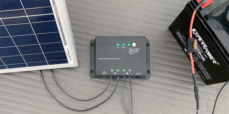
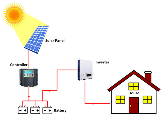
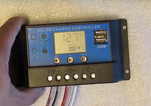
A solar charge controller, or solar charge regulator, is an important instrument in almost all solar power systems that use batteries as a chemical energy storage solution. It is used in stand-alone or hybrid solar power systems but not used in straight grid-tied systems, which don’t have rechargeable batteries.
Its two basic functions are very simple:
- Prevents batteries from overcharging
- Blocks the flow of reverse current.
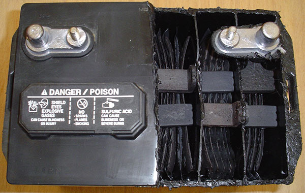
Overcharging can result in battery overheating, or, in an extreme possibility, a fire. Overcharged deep-cycle flooded batteries could also emit gas of hydrogen, which is explosive. What’s more, overcharging will quickly ruin the battery, thus shortening its lifespan dramatically.
Solar charge controllers can preclude the flow of reverse current from batteries to solar panels at night when the voltage of solar panels is lower than that of batteries.
Furthermore, solar charge controllers have other optional features, such as battery temperature sensor & compensation, Low-voltage disconnect (LVD), Load control (dusk to dawn), Displays, remote monitoring and diversion load control.
Let’s dive into the article to check these functions & features one by one.
Chapter 2: Charging a battery: Multi-stage charging
But before we dive directly into Chapter 3: Functions and features of a solar charge controller, we’d better take a look at necessary information about charging a battery.
If you are already quite familiar with this piece of information, you could jump to chapter 3 from here.

2.1 Brief interpretation
Imagine pouring water into a cup – at the beginning, you will pour at a faster rate; when the cup is close to full, water flow slows down so that the water will not overflow from the cup. On the contrary, if you keep pouring water at a faster rate, it’s hard for you to stop the flow in time at the end, and water will overflow from that cup.
The same theory applies to charging a battery:
- When the battery is low, the charge controller delivers lots of energy for a quick charge
- When the battery is close to full, it slows the charger by regulating its voltage and current.
- When the battery is full, it sends only a trickle of power to keep a full charge.
This is the so-called multi-stage charging.
2.2 Example: 3-4 Stages
Set Points:
In order to make sure you can easily understand the following content, which refers to an example of multi-stage charging (3-4 Stages), let’s firstly explain the jargon “set points.”
In brief,
the solar charge controller is set to change its charging rate at specific voltages, which are called the set points.
Set points are usually temperature compensated, and we will discuss this topic after the example of multi-stage charging.
Now, let’s go through the example in detail
The following is an example from MorningStar, which has 4 stages of charging.
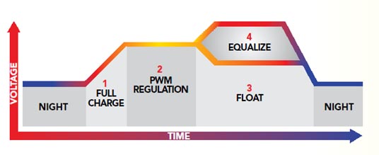
2.2.1 Stage 1: Bulk Charge
At this stage, the battery bank is low, and its voltage is lower than the absorption voltage set-point. So, the solar charge controller will send as much available solar energy as possible to the battery bank for recharging.
2.2.2 Stage 2: Absorption Charge
When its voltage reaches the absorption voltage set-point, the output voltage of the solar charge controller will keep a relatively constant value. Steady voltage input prevents a battery bank from over-heating and excessive gassing. Commonly, the battery bank could be fully charged at this stage.
2.2.3 Stage 3: Float charge
As we know, the battery bank is fully charged at the absorption stage, and a fully charged battery cannot convert solar energy into chemical energy anymore. Further power from the charge controller will only be turned into heating and gassing, as it is overcharging.

The float stage is designed to prevent the battery bank from long-term overcharging. At this stage, the charge controller will reduce the charging voltage and deliver a very small amount of power, like trickles, so as to maintain the battery bank and preclude further heating and gassing
2.2.4 Stage 4: Equalization charge
The equalize charge uses a higher voltage than that of absorption charging, so as to level all the cells in a battery bank. As we know, batteries in series or/and parallels constitute a battery bank. If some cells in the battery bank are not fully recharged, this stage will make them all fully recharged and complete all the battery chemical reactions.

Since it follows stage 3 (when the battery bank is fully recharged), when we raise the voltage and send more power to the batteries, the electrolytes will look like they are boiling. In actuality, it is not hot; it is hydrogen generated from the electrolytes, producing a lot of bubbles. These bubbles stir the electrolytes.
Stirring the electrolytes regularly in this way is essential to a flooded battery bank.
We can consider it a periodic overcharge, but it is beneficial (sometimes essential) to certain batteries, such as flooded batteries and not sealed batteries, like AGM and Gel.
Commonly you could find in battery specifications how long the equalization charge should last, and then set the parameter in the charge controller accordingly.
2.3 Why flooded battery banks need equalization
In short,
to preclude the sulfation of a lead-acid battery.
The chemical reactions of battery discharging generate soft lead sulfate crystals, which usually are attached to the surface of the plates. If the battery keeps working in this kind of condition, as time passes by, the soft sulfate crystals will multiply and become even harder and harder, making them pretty difficult to convert back to soft ones, or even further activate materials that were a part of the electrolyte.
The sulfation of lead-acid batteries is the scourge of a battery failure. This issue is common in long-term, undercharged battery banks.
If charged completely, the soft sulfate crystals can be converted back to active materials, but a solar battery is seldom fully recharged, especially in a not well-designed solar PV system, where either the solar panel is too small or the battery bank is oversized.
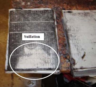
Only a periodic overcharge at high voltage can solve this problem; namely, equalization charging, which works at high voltage, generates bubbles and stirs the electrolyte. That’s why stage 4 is essential to a flooded battery bank. In many off-grid solar systems, we usually use a generator + charger to equalize the flooded solar battery periodically, according to the battery specification.
2.4 Control set points vs. temperature
Since absorption set-point (stage 2), float set-point (stage 3) and equalization set-point (stage 4) all can be compensated for temperature if there is a temperature sensor, we would like to spare some words for this little topic.
In some advanced charge controllers, multi-stage charging set-points fluctuate with the battery’s temperature. This is called a “temperature compensation” feature.
The controller has a temperature sensor, and when the battery temperature is low, the set point will be raised, and vice versa – it will adjust accordingly once the temperature gets higher.
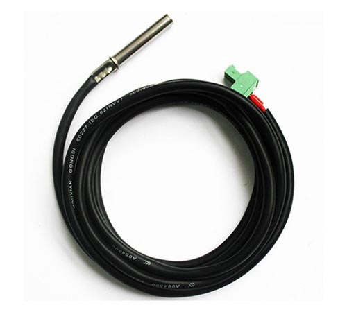
Some controllers have built-in temperature sensors, so they must be installed in proximity to the battery to detect the temperature. Others may have a temperature probe that should be attached to the battery directly; a cable will connect it to the controller to report battery temperature.
If your batteries are applied to a situation where temperature fluctuation is larger than 15 degrees Celsius every day, adopting a controller with temperature compensation is preferable.
2.5 Control set points vs. battery type
When we come to battery type, another article about solar batteries is recommended.
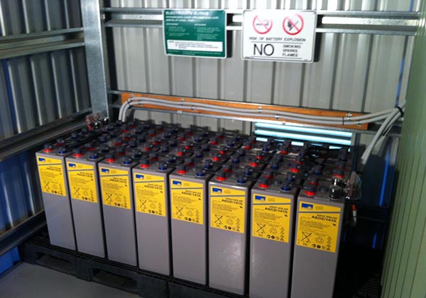
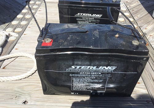
Most solar power systems adopt a deep-cycle, lead-acid battery, of which there are 2 types: flooded type and sealed type. A lead-acid flooded battery is not only economical, but also prevalent in the market.

Battery types also affect the design of set-points for solar charge controllers; modern controllers have the feature to allow you to select the battery types before connecting to a solar power system.
2.6 Determining the ideal set points
Finally, we come to the theory about determining the ideal set points. Frankly speaking, it is more about equilibrium between quick charging and maintenance trickle charging. The user of a solar power system should take various factors into consideration, such as ambient temperature, solar intensity, battery type and even home appliance loads.
It is necessary to only cope with the top 1 or 2 factors; that is enough in most cases.
Chapter 3: What is the function of solar charge controller?
3.1 Preventing overcharge
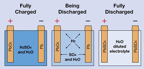
When a battery is completely charged, it cannot store more solar energy as chemical energy. But if power is continuously applied to the fully charged battery at a high rate, the power will be turned into heat and gassing, which would present as a flooded battery with a lot of bubbles from the electrolytes. That is the hydrogen gas, which is generated from a chemical reaction. These gases are dangerous since they are explosive. Overcharging also accelerates battery aging. And then we need a solar charge controller.
The main function of the solar charge controller is to regulate the voltage and current that is generated by solar panels going to the batteries to prevent batteries from overcharging and guarantee the batteries a safe working condition and a longer lifespan.
There are 3 types of regulators:
1. Current regulator
A current regulator acts like a switch. It simply switches the circuit on or off to control the energy flow to the battery bank, just like stage 1 bulk charging. They are usually called shunt controllers, which are no longer used due to their obsolete technology.
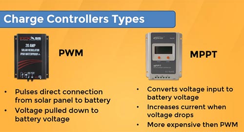
2. Pulse width modulation (PWM)
Shunt controllers shut down the current completely, while the PWM controller reduces the current gradually. PWM is more similar with stage 3 float charging.
We will have an in-depth discussion about PWM and MPPT when we start the topic: PWM VS MPPT which one is better.
3. Voltage regulator
Voltage regulation is common. The solar charge controller regulates the charging in response to the battery voltage. It is quite simple. When the voltage of a battery reaches a certain value, the controller protects the battery from overcharging by reducing the power. When the voltage of a battery drops because of a large sum of power consumption, the controller will allow bulk charging again.
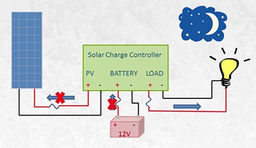
3.2 Blocking reverse current
The second main function is to prevent reverse current flow.
At night, or whenever there is no sunlight, the solar panel does not have power to convert into electricity, and, in a solar power system, the voltage of the battery bank will be higher than the voltage of the solar panel, since we all know electricity flows from high voltage to low voltage. So, without a charge controller, the electricity will flow from the battery bank to the solar panel, which is a waste of power, as the solar power system takes efforts to collect energy during the day but wasting a little of them at night. Although the loss is only a little in proportion to the total energy collected, it is not hard to solve.
A solar charge controller can deal with this problem.
Most controllers allow the flow to go only from solar panel into a battery bank by designing into the circuit a semiconductor, which only passes currents in one direction.
Some controllers have a mechanical switch, which is also called a relay. When the relay clicks on and off, you will hear a clatter sound. When the voltage of the solar panels is lower than that of the battery bank, it detects and then switches off the circuit, disconnecting the solar panels from the battery bank.
3.3 Load control
Some solar charge controllers are designed with load control, allowing you to connect a DC load, such as an LED lamp (a concrete example is on our website all-in-one solar LED street lights), direct to the solar charge controller, and the load control will turn the lamp on and off according to its pre-settings (the voltage of battery, photocell sensor, or a timer).
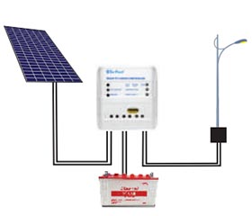
For example, there commonly are timers in LED solar street lights, and the load control will read the time from the timer and then execute the command: turn the LED on at 7:00 pm at dusk and turn it off at 6:00 am the next morning. Or the load control will read information from the photocell sensor and then control the LED on and off according to the brightness of the ambient environment.
3.4 Low voltage disconnect (LVD)
Imagine that you are boiling water in a pot and you forget to turn off the fire until the boiling water is totally evaporated; no longer any water in the dry pot and the pot overheats. The pot is destroyed permanently. In the same way, discharging a solar battery completely will result in permanent damage to a battery.

Deep cycle batteries are widely used in solar power systems. The Depth of Discharge (DOD) could be as large as 80%; however, they are susceptible to permanent damage if discharged up to 90% or, even worse, 100%.
If you wait to switch off the DC load from your batteries until you find your lights dimming, the battery damage could have already happened. Both battery capacity and life expectancy will be decreased every time when over-discharge happens. If the battery were set to work in this kind of over-discharge state for a period of time, it would be ruined quickly.
The only practical solution to protect batteries from over-discharge is to switch loads (such as appliances, LED lights and so on) off and on, provided that the voltage has recovered from bulk charging.
Typically, if a 12V battery drops to 10.9 volts, the battery would be on the verge of over-discharging. In the same way, 21.9 volts for a 24V battery.
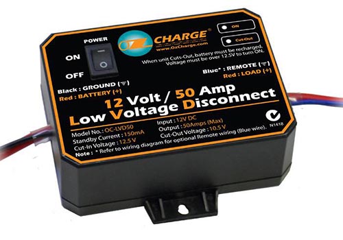
If your home solar system has some DC loads, the LVD feature is necessary. Some LVDs are integrated into charge controllers while others aren’t.
3.5 Overload protection
When the input current flow is much higher than what the circuit can safely deal with, your system overloads. This can lead your system to overheat or even cause a fire. Overload can be caused by different reasons, such as a wrong wiring design (short circuit), or a problematic appliance (a stuck fan). Commonly, a push-button reset is designed for the overload protection circuit.
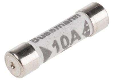
However, there is a built-in overload protection in each solar charge controller; large solar power systems usually require double safety protection: fuses or circuit breakers. If the wire carrying capacity is smaller than the overload limit of the controller, then setting up a fuse or breaker in your circuit is a must.
3.6 Displays
The displays of solar charge controllers vary from LED indicators to LCD screen displays, with information of voltage and current. Displays to solar power systems are what console dashboards are to cars. They provide you with detailed data so that you can monitor the state of your battery bank: how much energy you are using or generating.
If your system already has a self-contained monitor, then the display feature would not be important. Even the cheapest monitor would include basic meters, just as controllers have.
Chapter 4: PWM charge controller
4.1 Need-to-know glossaries
At the beginning, we will go through some glossaries – refer to the following table.
| Nominal | Cells | Voc | Vmp |
| 12V | 36 | 22V | 17V |
| 20V | 60 | 38V | 30V |
| 24V | 72 | 44V | 36V |
- Voc, open-circuit voltage, is the maximum voltage across a PV cell, when you measure a solar panel in theoretically standard test conditions (STC) with only a voltmeter connected. The voltage the meter receives is the Voc.
- Vmp, voltage at maximum power, is the output voltage of solar panels when connected with the PV system.
- Nominal Voltage is a reference voltage used to categorize solar equipment in an off-grid system. In a grid-tied system, the nominal voltages (12v, 24v and 48v) are meaningless.
Although charging a battery requires higher voltage, nominal voltages can help you find out corresponding equipment (such as a battery bank) with which a solar panel can match.
So,
a 12V solar panel actually has Voc of 22V and Vmp of 17V, with 36 pieces of silicon squares on the front side.
Similarly,
the 24V solar panel has Voc of 44V and Vmp of 36V, with 72 pieces of silicon squares.
You might be wondering: why a 12-volt panel is not 12 volts?
here’s the deal.
4.2 Why 12-volt panels are 17 volts
A fully charged 12V battery is actually approximately 12.6 volts; to charge a 12V battery, we need higher input voltage – about 13.7-14.4 volts from a solar panel. But why did we design the solar panel Vmp to 17V and not just 14V?
A Voc of a solar panel is measured under Standard Test Conditions or STC, and Vmp is also measured under STC, where the ambient temperature isn’t too hot, the intensity of sunshine is perfect – no clouds, no haze. However, we are not always that lucky. If we encounter some bad weather – for example, hazy or cloudy days – the voltage of a solar panel will drop; so, the panels should be designed with some extra voltage so that your system can still receive enough voltage, even if the weather is not ideal; i.e. no sunlight.
4.3 Charge controller types:
There are 3 types of solar charge controllers:
- Shunt controllers
- PWM
- MPPT
Shunt controllers: We mentioned shunt controllers when we talked about current regulation – they act just like a switch, turning on and off the flow of current to a battery. You may still see a few on old systems, although they have already been taken off the market. PWM and MPPT are the 2 main types that prevail today.
Now
Let’s go into PWM first.
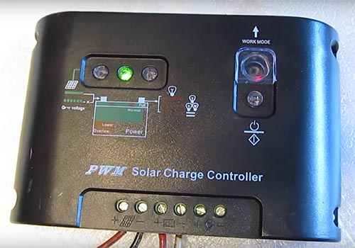
4.4 What is PWM solar charge controller?
PWM (Pulse Width Modulated), literally, works by modulating its current pulse width.
PWM sends to the battery intermittent charging pulses rather than a steady power output. It operates more like stage-3 float charging that generates trickles of currents to battery.
But how fast (frequency) and how long (width) the pulse should be produced is determined by the state of the battery it detects. If the battery is already fully charged, and the loads in the system are not working, the PWM will only send a very short pulse every few seconds; for a discharged battery, the pulses would be near to continuous. This is the basic working principle.
Although PWM is less expensive than MPPT, because of the sharp pulse the PWM generates, when processing a rapid on and off switch during working, your TV, radios or telephone signals may often be interfered with. That’s the inherent downside of PWM.
When your system chooses PWM as the charge controller, it is important to make the nominal voltage of solar panels the same as the nominal voltage of a battery bank;
namely,
if your battery bank is 12V, you must select 12V solar panel as well.
And if your battery bank is 24V, then you must use a 24V solar panel, or wire two 12V solar panels in series, to make it a 24V.
But if your battery bank is 48V, then you need to wire four 12V solar panels in series, or two 24V solar panels in series, to get 48V.
And so on.
Meanwhile, make sure the PWM specifications match that of your battery bank, too.
4.5 How big of a solar charge controller do I need: PWM
How to size a PWM when we design an off-grid PV system?
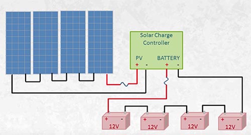
Step 1, Get the Isc (Short Circuit Amps) and the Voc (Open-Circuit Voltage) solar panel from its nameplate, and figure out how many strings in parallel are in the solar array.
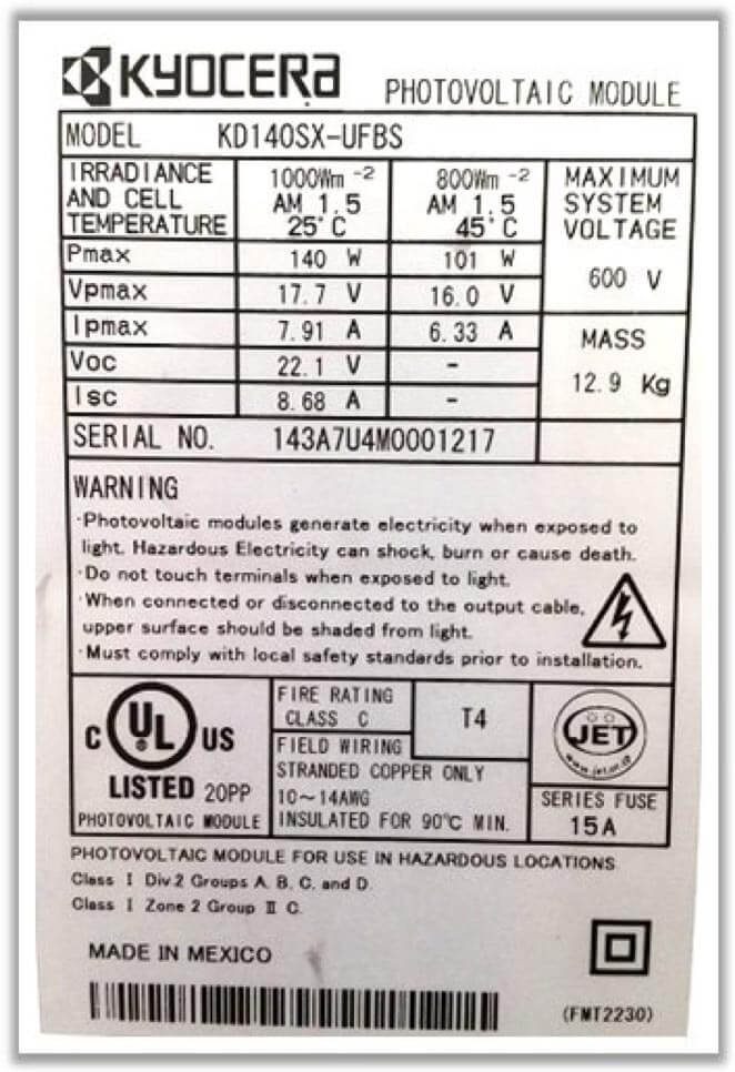
From the nameplate,
we read the Voc 22.1V and Isc 8.68A, and we confirm that it is a nominal 12V solar panel from Voc.
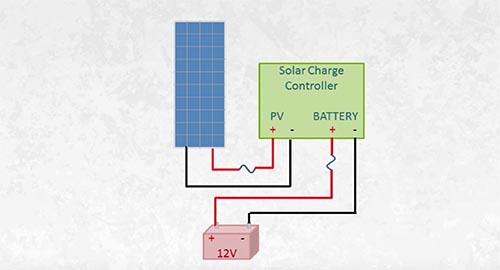
Let’s start with a simple example and assume we only have 1 string in parallel.
Step 2, Multiply Isc by the number of strings in parallel.
8.68Isc x 1 string = 8.68A
Step 3, multiply by 1.25 safety factor. (Why the factor is 1.25: refer to NEC 690.8(A)(1) Photovoltaic Source Circuit Currents)
8.68Isc x 1 string x 1.25 = 10.85A
So, we can choose a PWM that’s current load capacity should be larger than 10.85A.
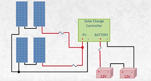
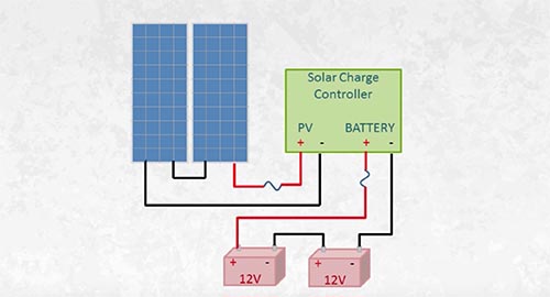
Now, let’s check another example with 2 strings in 2 parallels using the same 140w panel mentioned just now.
But do remember – we are using a PWM charge controller, so we need to pay attention to how many panels are in strings so that the voltage of the solar array matches the voltage of the battery bank.
In this example, we have 2 parallel strings and 2 panels in series, so the solar array is for 24V battery system.
8.68Isc x 2 strings x 1.25 = 21.7A
A 25A PWM solar charge controller would be enough.
Chapter 5: MPPT charge controller
5.1 How does a MPPT solar charge controller work?
What is the meaning of MPPT?
MPPT is the acronym for Maximum Power Point Tracking, which is a type of electronic digital tracking.
MPPT is more sophisticated – and also the more expensive – of the two. MPPT has around 94% – 98% conversion efficiency. That is power in (from the solar panel) almost equals power out (to battery bank).
The MPPT charge controllers read the output of solar panels and the voltage of batteries to figure out the best power point to draw from solar panel; then, the MPPT turns the voltage down to meet the battery charging voltage while raising the current. By doing this, the MPPT can increase energy that we finally get from solar panels by almost 40%, compared with PWM, since PWM cannot increase current to track the maximum power point.
Unlike PWM, which requires the voltages match with both sides, MPPT can be applied to the PV system, which voltage of solar array is higher than that of the battery bank. This feature brings the MPPT many advantages, which we will discuss in Chapter 6
Now,
let’s move on to the examples so that you can catch the point quickly.
5.2 How to size mppt solar charge controller?
Remember the nominal 20V panels with 60 pieces of cells?
In the PWM circuit, they are too large to match a 12V battery bank and too small for a 24V battery bank, but the MPPT can solve this embarrassing situation.
The 20V panel has 30Vmp and 9A Imp, and its rated power = 30 x 9 = 270W.
Assume the 20V panel applies to the 12V battery. The MPPT will convert 30V down to around 14V to charge the battery, and increases the current so that it can draw maximum power from the solar panel.
If we take 30V down to 14V, the decreased rate is
30/14 = 2.14.
Then the increased current is
9 x 2.14 = 19.28A.
Finally,
30 x 9 = 14 x 19.28 = 270 watts (power in equals power out);
since the output current is 19.28A, we multiply by 1.25 safe factor.
We get
19.28 x 1.25 = 24.1A.
So, it will be good that we choose an MPPT with a current capacity larger than 24.1A.
Another example with 2 strings in 2 parallels using the nominal 20V panel to charge the 12V battery: the total power in is
270 x 4 = 1080 W.
The current output would be
1080 / 14 = 77.14A.
Multiply by 1.25
77.14 x 1.25 = 96.43A.
So, we are going to choose a 100A MPPT.
5.3 Charge controller sizing: the voltage of the controller
One more thing we need to pay attention to when sizing a solar charge controller is the voltage. Make sure the controller is capable of carrying input voltage from the panels. A 150V charge controller can only carry three 20v nominal panels in series. You may wonder…3 x 20 = 60V? That is far away from 150V!
Why?
That is because the actual voltage that solar panels generate could be much higher than 20V; sometimes, higher than the Vmp 30V. So, we use Voc to do the calculation. Voc = 38V.
3 x 38 = 114V
Then three nominal 20V panel in series is 114V
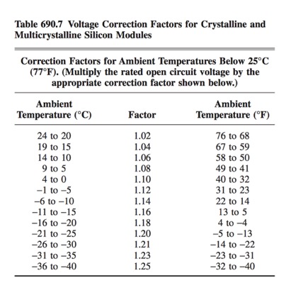
Since panel voltage will increase in the cold weather, refer to the NEC Table 690.7. Then we pick up the safest factor, 1.25, multiply 114v by 1.25,
we get
114 x 1.25 = 142.5V.
Now you can understand why a 150V controller can only support three 20V in series, especially in winter.
Nowadays, newly developed controllers could have much higher voltages; some models even support as much as 700V input. This is very important when your solar array is settled far away from your battery bank.
Let’s explore the reason in chapter 6.
Chapter 6: PWM vs. MPPT
6.1 PWM vs. MPPT: Which one is better?
We have learned about the features of both controllers (PWM & MPPT) in previous chapters. We well noted that PWM does not convert extra voltage into currents, which results in low power conversion rates. In other words, PWM doesn’t transfer all energy that is collected by solar panels to batteries, but MPPT is always tracking the maximum power point from the panels and adjusting its currents and voltage accordingly so that it can transfer all energy collected by solar panel to battery.
A concrete example will explain this clearly:
The basic physical formula:
Power (watts) = V (Volts) x I (Amps)
If we use a nominal 12V, 100W solar panel to charge a 12V battery system, the actual Vmp is 17V, and we can calculate its current output:
I = Power / V
I = 100 / 17 = 5.88 amps
Now we know the panel output is 17V and 5.88A.
Scenario 1: The photovoltaic system is with PWM solar charge controller.
PWM will drag the voltage down to battery charging voltage – approximate 14V. After going through the PWM, the solar energy only remains 14V and 5.88A.
That is:
P = V x I = 14 x 5.88 = 82.32 W
Scenario 2: The photovoltaic system is with the MPPT solar charge controller.
The MPPT not only drags the voltage down to 14V, but also increases the current, so that the power almost equals to power out.
So, if the voltage decreases by 17/14 = 1.21
Then the current to battery increases by 1.21, we get
5.88 x 1.21 = 7.11A
Total power out
P = 14 x 7.11 = 99.54 W
In this example, the power wasted by PWM is
99.54 – 82.32 = 17.22W
Almost 20% energy was not converted to battery chemical energy. If we consider the scenario in a large solar array, the loss could be tremendous.
So, it’s better to use MPPT for large solar array.
6.2 The strengths of MPPT
a) High conversion efficiency
If your photovoltaic system comes with a large solar array, MPPT would be the best choice to boost the solar energy conversion, especially in cold weather, since the panel voltage will rise as the temperature drops. The MPPT conversion rate could rise from 20% to 40%. That’s green and free energy that really saves money on your bill.
b) Lower energy loss in cables or lower cost for purchasing cables.
Please remember Ohm’s law formula
V (Volts) = R (Ohm) x I (Amps)
Output power PO (Watts) = V (Volts) x I (Amps)
So
Resistance loss PR(Watts) = R (Ohm) x I2 (Amps)
Then, if your PV panels are installed a long distance from your battery bank, the power loss of cable resistance is considerable ( PR = R x I2 ). Here R represents the resistance of cables. R increases as cable length increases:
But if we double the Voltage of the solar array by wiring them in more series, according to PO = V x I, there is no change of total power outputPO , so the current through cable I should be half.
Finally, the resistance PR(Watts) = R (Ohm) x I2 (Amps) will be a quarter than before.
In fact, with MPPT, you could raise the voltage of the solar array even higher to reduce the current flow.
In this case, we increase the panel’s voltage to reduce the resistance loss through cables, and since we are using MPPT, which always tracks to harvest maximum power from panels, we have no voltage waste as PWM may have.
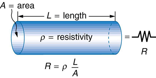
We could review this topic from another aspect. If you cannot raise the panels voltage, then you have to find out some solution to reduce cable resistance, as resistance = resistivity × length / area, it seems the only way is to use cables with large transverse areas, and that will be another huge sum of money to spend.
To recap, when it comes with small systems, PWM is a good solution since it is inexpensive, but for large systems, in order to improve conversion rates and not waste the solar panel capacity of harnessing solar energy, MPPT is preferable. MPPT would always be applied to higher power systems.
6.3 Pros and cons
Learning knowledgeable information from the previous content is necessary before making the decision to purchase a solar charge controller for your PV system. A comparison table, listing the difference between PWM and MPPT, is also suggested. So, we put their pros and cons together to make it more convenient for you to review.
| Pros | Cons | |
| PWM | PWM technology has been available in PV systems for a long time and is a relatively stable and mature technologyThey are cost-effective and are affordable for most consumersPWM can withstand up to 60 amps load currentlyMost PWMs have a reasonable heat dissipation structure that allows them to work continuouslyPWM comes in different sizes to suit a wide range of applications | If PWM is applied to photovoltaic solar systems, the voltage of the solar panel has to match that of the battery bankThe current load capacity of a single PWM has not been developed and is still only up to 60 ampsSome smaller sized PWM charge controllers cannot be UL listed due to their poor structure designSome smaller sized PWM do not have fittings of conduitPWM has signal interference problems sometimes. The controllers generate noise in TV or radiosPWM limits the expansion of photovoltaic solar systems to some extentIt cannot be applied to high voltage off-grid solar arrays |
| MPPT | MPPT maximizes the conversion of solar energy from PV panels, and the rates can be 40% more efficient than PWMMPPT can be used in cases where the solar panel voltage is higher than the battery voltage.MPPT can withstand up to 80 amps load currentMPPT features longer warranties than PWMMPPT does not limit the expansion of solar panels in the systemMPPT is the only solution for a hybrid solar power system | MPPT are more expensive than PWM. The pricing of some models is double that of a PWM charge controllerSince MPPT has more components and functions, its physical size is larger than PWM.MPPT are more complicated, so most time, we need to follow a guide when sizing the solar arrayMPPT solar controller constantly compels the solar panel array wired in strings |
6.4 Does every solar PV system need a charge controller?
The answer is no.
Generally, if your solar panel is less then 5 watts for every 100 amp hours battery, then you do not need a solar charge controller.
Here is a formula we can use:
Quotient = Battery Capacity (Amp Hour) / Imp of solar panel (Amps)
If the quotient is larger than 200, you don’t need a controller; otherwise, you’d better install a controller.
For example, if you have a 200AH battery and 20W panel, the quotient would be 200/1.18=169.5; in this case, you need a controller.
If you have 400AH battery and 10W panel, the quotient would be 400/0.59=677.9; in this case, you do not need a controller.
Glossaries
- Set Points: The specific voltages that were set for charge controllers to change charging rates.
- DoD: Depth of Discharge, the proportion of battery capacity (amp hours) removed from a fully charged battery. For example, if total battery capacity is 100 Ah and 40 Ah is already discharged, then the DoD is 40%.
- Deep Cycle Battery: Lead-acid battery, which can always be deeply discharged to a low state-of-charge. Deep cycle batteries have high DoD.
- Imp: Current at maximum power; the quotient of maximum power by Vmp.
- STC: Standard test conditions, ideal conditions in a laboratory where a fixture is tested.
- Voc: Open-circuit voltage, the maximum voltage across a PV cell, when you measure a solar panel in theoretically standard test conditions (STC) with only voltmeter connected. The voltage the meter gets is the Voc.
- Vmp: Voltage at maximum power, the output voltage of a solar panel when it is connected to the PV system.
- Nominal Voltage: A reference voltage used to categorize solar equipment in an off-grid system. In a grid-tied system, the nominal voltages (12v, 24v and 48v) are meaningless.
- Isc: Short-circuit current, the maximum current across an external circuit that is without any loads or resistance.